


Featured Blogs

Featured Solutions
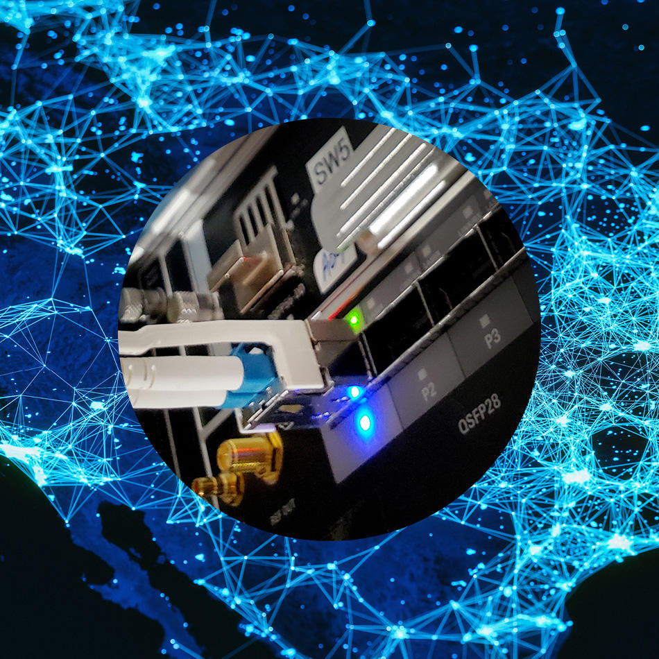


The Communications Leader
Discover our communications solutions for datacom and telecom.
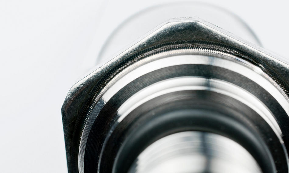
Advanced thermal management
Engineered materials deliver advanced thermal management qualities.
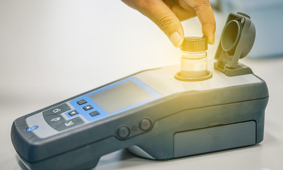
Wearable health monitors
Bio-sensing functions are a cornerstone of modern health monitors.
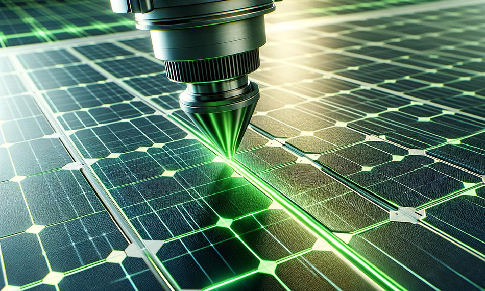
Glasgow: Ultrafast Lasers
Coherent Glasgow is the center for our ultrafast laser manufacturing.
Featured Event
The Battery Show Europe
June 18 - 20, 2024
Stuttgart, Germany, Booth D40
The Battery Show Europe is the leading meeting place for the advanced battery and H/EV technology community. Visit us at booth 8-D40 and find out how laser technology can be used in battery production.

Featured Products
MATERIALS FOR OPTICS, PHOTONICS, AND ELECTRONICS
Get the highest-quality materials and secure supply chain resiliency from the recognized leader.

Coherent Careers
Our multidisciplinary team of scientists and engineers radically reimagine what’s possible by creating custom solutions for our clients.

Coherent Labs
Solving the most difficult manufacturing challenges with thought leadership and innovative laser systems solutions. Our experts engage customers on over 2,500 projects per year.

Shop Coherent
Online shopping for lasers, optical fibers, power meters and sensors, accessories, and much more on Coherent online has never been easier.